|
|
|
www.conserver.com |
|
|
|
www.conserver.com |
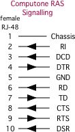
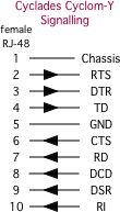
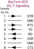
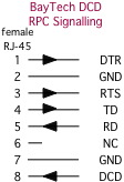
Use the links below to select which interface your connector uses, then look for your device in that section. (If you don't find the device wiring you are looking for here, and you later find the information somewhere else, please let me know where you found the information, so I can update my page.)
 |
 |
 
|
 |
 |
 |
 |
 |
 |
 |
 |
 |
 |
 |
 |
 |
 |
 |
 |
 |
 |
 |
 |
 |
 |
 |
 |
 |
 |
 |
 |
 |
 |
 |
  |
 |
  |
 |
  |
 |
|
|
There is no formal standard for using a 1/8-inch "mini-phone" connector (also referred to as a "Tip-Ring-Sleeve", or TRS conector) for serial connections. The normal jack has two connections (the "tip" and the "sleeve". A stereo jack has a third connection (the "ring"). If you are going to use this jack for 2-way, RS-232 serial communications, you need at least three wires (signal reference (ground), receive data (RD), and transmit data (TD)) in order to work. Your connection will not have any hardware flow control or hardware handshaking in this configuration.
While this jack format is becoming popular for smaller, handheld devices, it is frequently NOT an RS-232 interface! That is, the signal levels are typically a positive signal and ground for the signaling, versus a positive and negative signal level used in RS-232. As a result, most of the "serial cables" sold for these devices include a 'level converter' circuit in the DB connector. Before you try to connect a device using a TRS connector to a serial port, you should read the documentation (or take voltage measuremens), and be SURE that the connection uses RS-232 voltage levels before you connect it to a serial port. (It is possible for the RS-232 voltage levels on your serial ports to cause severe damage to any non-RS-232 circuitry in some handheld equipment!) Check the MassMind.org website for more information about TTL to RS232 signal level conversion.
That said, the Adaptec FS4500 storage shelf uses such an interface, with RS-232 levels. The 'tip' is data from the device, the 'ring' is data going into the device, and the 'sleeve' is the signal reference ground. It uses an adapter cable (p/n CBL-00012-02-A) which uses a DE9F interface on one end. Pin 2 of the DE9F goes to the 'tip', pin 3 goes to the 'ring', and pin 5 goes to the 'sleeve'.
 |
 |
 |
 |
|
||
  |
Because the RS-232 physical wiring standard for async signals is so widely deployed, I'll simply list the 'standard' schema for DTE and DCE interfaces for both connector types.
 |
 |
 |
 |
You can refer to any of my Host-to-Adapter guides for information about the DB-n serial ports on a variety of devices. If the host is listead as being "MDTE", it means that the device has a male DB-25 serial port, with the DTE signalling shown here. (Following this logic, a host listed as "FDCE" would be a Female DB-25, with DCE signalling...)
Devices with a DE-9 serial port are listed as "MDTE9n" (for a Male DE-9, wired for DTE signalling), where 91 means that the device doesn't assert, or care about, the DCD signal. (Hosts shown with a 92 suffix assert or may require DCD, so make sure that your cables or adapters are wired accordingly!)
|
NOTICE: Most of the pages, articles, and tutorials on this website are copyrighted works. You may make 'deep links' to various pages. (If you let me know which page(s) you are linking to, I'll let you know if I move the page(s) during updates.) Please send me email if you wish to republish any material, or use it on your own website. |